

Development of hydraulics for a Francis turbine with nq=66
For the start geometry of the runner blade hydraulics, we took recourse to the approaches of SIERVO and THOMANN which several times already proved to be useful for Francis turbine designs. Whereas THOMANN bases his choice of the main turbine dimensions on the specific speed ns (=3.65*nq), according to SIEVO the main dimensions not only depend on the specific speed but additionally on the head-dependant runner diameter D3 (or the draft tube connection diameter DS).
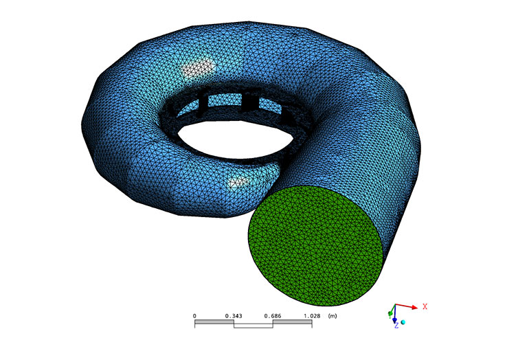
For the blade profiles the 4-digit NACA profile NACA-0006 was used. In order to facilitate mesh generation and for the structural fragmentation into the areas “spiral”, “guide vane”, “runner”, “draft tube” and “outtake”, the hydraulic contour of the whole Francis turbine was split up.
For the generation of the guide vane and runner meshes ANSYS Turbogrid V11 was applied. In order to achieve adequately refined efficiency curves during the numerical flow simulation process, the guide vane positions were displaced by steps of 2.5°. Finally, the draft tube and the outtake of the Francis turbine were structurally meshed with structured grids by means of ANSYS-ICEM V11.

Francis turbine hydraulic: efficiency and cavitation
For the examination of the machine’s cavitation behaviour the so-called Thoma number – Sigma – has to be calculated, whereas a difference has to be made between the Thoma number of the plant Sigmaplant and the Thoma number of the turbine Sigmaturbine (which is normally measured by means of model tests). To ensure cavitation-free operation of the turbine, in any case Sigmaturbine (or Sigmalimit) has to be lower than Sigmaplant . Experimental values gathered from past experiences are: Sigmalimit = 1.04 *SigmaCFD, histogram, 0.005.
Optimisation of the Francis turbine hydraulic by CFD
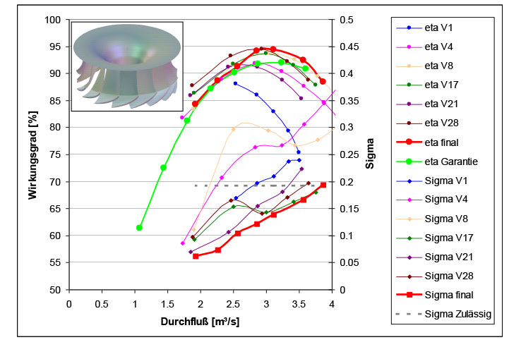
For the optimisation of the Francis turbine described herein, a simplified mesh has been used for every single type of guide vanes and runner blades. The efficiencies depicted in the diagrams have already been adjusted downwards by 0.3% for the intake and outtake areas, as experiences from previous projects as well as comparisons with test results have shown that consideration of simplified calculation models – this means the non-consideration of the spiral and the support vanes – provides a slightly higher level of efficiency which is corrected by subtraction of the value 0.3. The exact numeric result will be found by means of the complete, however time consuming calculation model anyhow.
Altogether, more than 35 (!!!) different variants of hydraulics have been examined and compared during this project. The figure above illustrates that the efficiency could be increased step by step, and in parallel the Sigma value could be reduced – that is to say improved. The best efficiency could be reached with the runner blade variant V31 in combination with the original guide vane version. However, since the cavitation behaviour still was not satisfactory, the complete hydraulic system has been enlarged by the factor 1.03 which causes a reduction in speed – or an increase of the optimum flow rate – and thus allows for the realisation of higher pressures and better cavitation behaviour.
Furthermore, the Sigma curve for this runner blade variant seems to be nearly perfect. These findings are emphasised by a comparison with the references according to Siervo and Thomann, which point to Sigma values between 0.14 and 0.16 in the optimum – compared to the value of 0.135 we calculated. Cavitation-free operation of the Francis turbine could be proven numerically.
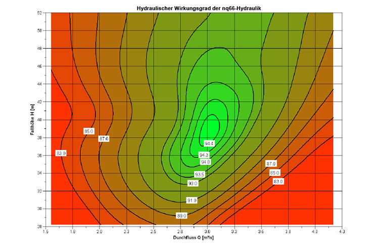
Referring to the efficiency shell, the following has to be stated: In case, this shell is converted into the dimensionless coordinates φ and ψ, the hydraulics thus determined are applicable for all operating point of the Francis turbine, which provide the same φ-ψ-combination for all speeds.
Core competences
Our services for turbines
- Product development
- Designing
- Optimisation
- Refurbishment
- Troubleshooting
» Details
We do research, development and optimisations for
- Hydraulics for turbines / pump turbines / pumps
- Acceptance tests acc. to IEC standards
- Nozzels
- Spirals
- Turbine in- and outtakes
- Valves & fittings
- Runners, guide vanes
- Water hammer
- Seals
- Surge chamber
- Penstock
- Refurbishment
- Efficiency
- Life cycle
- ...
We solve your challenge. Contact us.