

Water hammer protection in a drinking water hydro power plant
The head race tunnel of this drinking water hydro power plant, the pipelines and the fittings as well as the Francis turbine installed have been modelled by means of a simulation network.
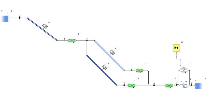
The system consists of a higher reservoir with constant water level – a long rock tunnel which has been regarded as circular. Following this reservoir, the water volume is being divided into two parallel pressure pipelines. At the end of each of these two pipelines a shut-off valve is installed. In case of a load rejection, the Francis turbine is responsible for the occurring water hammer. Nevertheless, the complete hydraulic behaviour of the machine has been taken into account for the calculations. For the necessary engine characteristics the manufacturer could be addressed directly.
As usual, different operational modes and extreme load cases have been examined. For example, it was considered that the auxiliary outlet valve will not be opened so that the maximum possible water hammer is going to occur. Of course, amongst other load cases and operational modes the regular functioning of the bypass valve has been investigated as well.
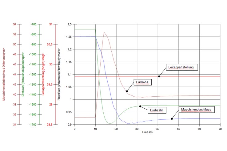
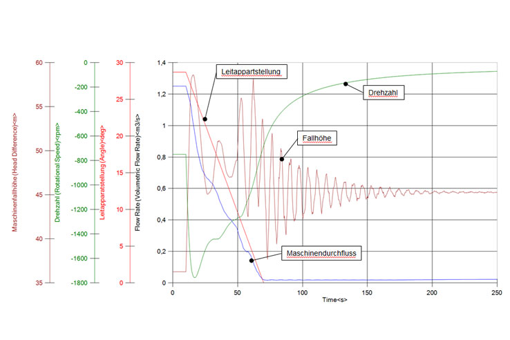
The increase of the machine head and thus of the static pressure in the pipelines as of the increasing rotational speed of the turbine after load rejection, which was simulated in calculation seconds 10 [s], is obvious. This increase of the machine head is caused by the given flow rate reduction as of the machine characteristics and the resulting water hammer and pressure increase before the turbine. The figure displays the same machine parameters for a regular emergency shut-off.
By calculating the pressure envelopes for the different operational and special load cases (much more than the two examples depicted), not only the permissible pressures could be defined but the necessary parameters for the calculation of the plant’s lifetime could be made available as well. As the figure above shows – and as is well known – in practice, the plant has to undergo all anticipated and unforeseen operational modes and thus numerous more or less extreme load changes, which rather cannot cause more wear than the maximum load and thus have to be analysed separately.
In case of normal functioning of the plant and in case that all control measures foreseen are being taken, no water hammer risk occurs. The designed operational mode of the drinking water hydro power plant causes no inadmissible exceeding of the maximum internal pipeline pressure permitted. However, it has to be mentioned that in case of a failure and of an abrupt disconnecting of the generator from the electricity network an inadmissible pressure increase in both pressure pipelines at certain identified parts has to be expected. Furthermore, certain activities could be identified which – in case of an emergency shut-off – lead to water hammer increases in front of the turbine, whereas these increases can be eliminated by appropriate locking devices which enable safe operation of the power plant without excessive security measures and investments.